1. ບົດແນະນຳ
This manual provides detailed instructions for the installation, operation, and maintenance of the Acouto Low Voltage Relay Module, Model YYC-7. This versatile time delay relay is designed for a broad range of applications, offering wide power compatibility and memory retention for settings.
The module operates on a broad voltage range, starting from 3V, making it compatible with various power sources such as 3.7V lithium batteries, 5V power banks, or standard switching power supplies. It is suitable for controlling motors, light bulbs, LED strips, DC motors, and pumps. Featuring output optical coupling isolation, the module offers enhanced anti-interference capabilities and an industrial-grade circuit board for durability. Its parameter-saving function ensures that settings are retained after a power failure.
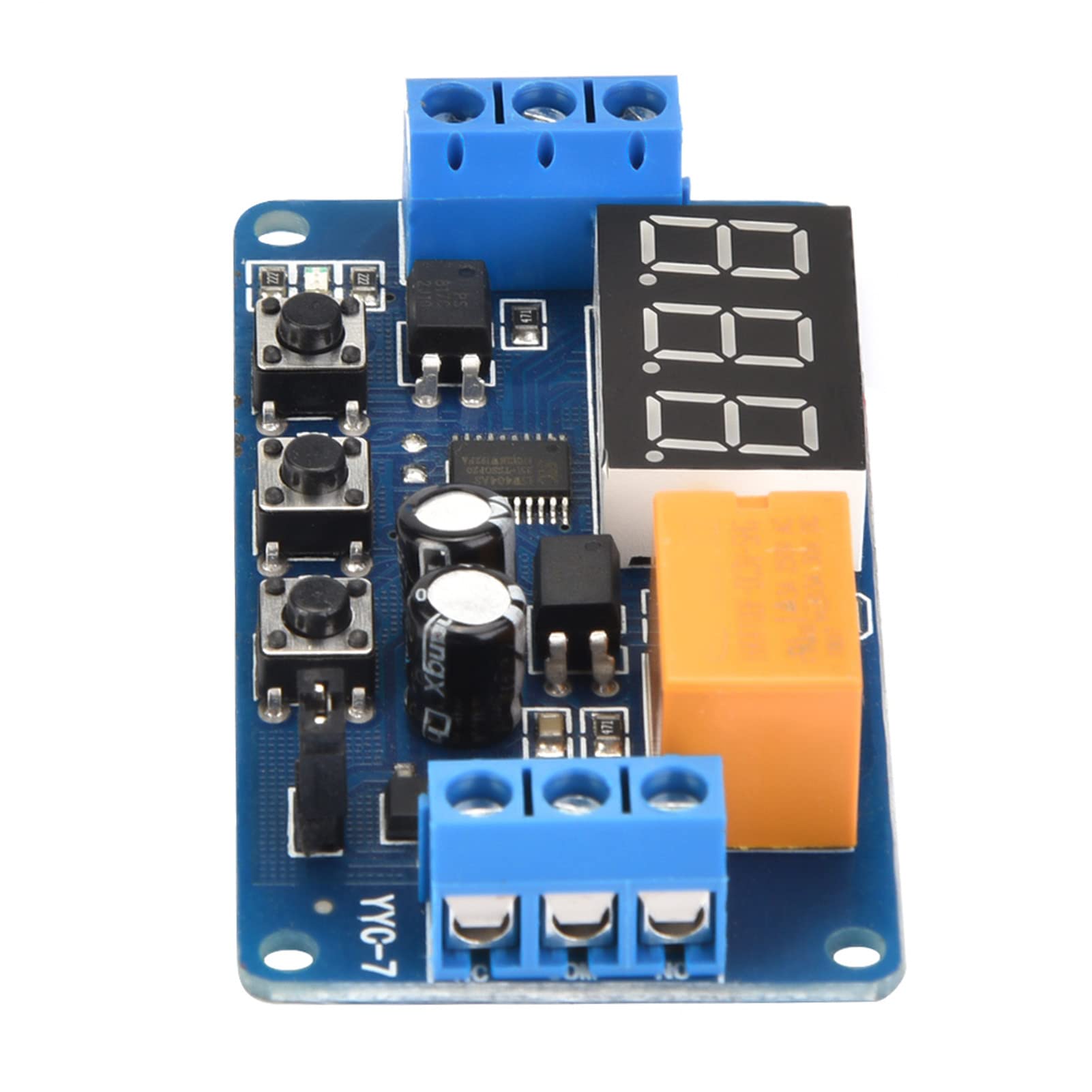
Figure 1: Acouto Low Voltage Relay Module (Model YYC-7)
2. ຂໍ້ມູນຄວາມປອດໄພ
- ໃຫ້ຖອດສາຍໄຟອອກກ່ອນຕິດຕັ້ງ ຫຼື ບໍລິການໂມດູນສະເໝີ.
- Ensure all wiring connections are secure and correct to prevent short circuits or damage.
- ຢ່າເກີນ vol ທີ່ລະບຸໄວ້tage and current ratings for the module and its output.
- This module is intended for use by individuals familiar with electronic components and wiring.
- Keep the module away from moisture, extreme temperatures, and corrosive environments.
3. ຜະລິດຕະພັນເກີນview
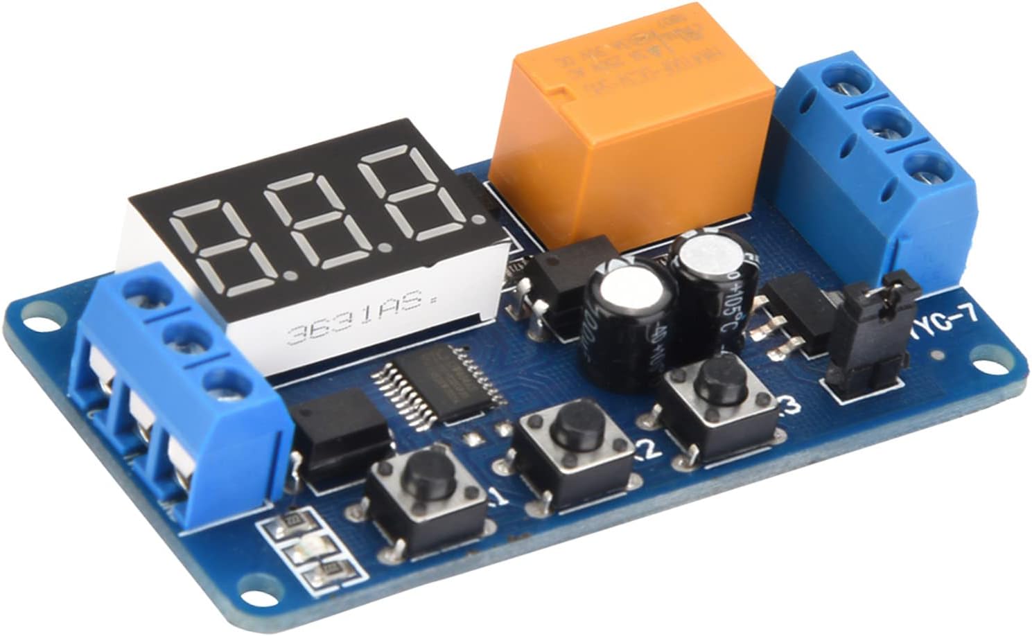
The Acouto YYC-7 module features a digital display, control buttons, and terminal blocks for power and load connections. Understanding these components is crucial for proper operation.

Figure 2: Labeled Components of the YYC-7 Module
ອົງປະກອບທີ່ສໍາຄັນ:
- ການສະແດງເວລາ: A 3-digit LED display shows current time settings or operating status.
- ຖ່າຍທອດ: The orange component responsible for switching the load.
- ແສງຕົວຊີ້ວັດ: Provides visual feedback on the module's status.
- Adjustment Buttons (K1, K2, K3): Used for mode selection and parameter setting.
- Jumper: Configures the working voltage ຊ່ວງ.
- Terminal Blocks: For connecting DC power (DC+, DC-), signal input, and load (NC, COM, NO).
4. ຂໍ້ມູນຈໍາເພາະ
| ຄຸນສົມບັດ | ຂໍ້ມູນຈໍາເພາະ |
|---|---|
| Working Current (with jumper) | DC 3V ~ 5.5V |
| Working Current (without jumper) | DC 3.8V ~ 7V |
| Signal Source Voltage | DC 3V~12V (e.g., positive actuator, button, PNP sensor, PLC) |
| ຄວາມອາດສາມາດຜົນຜະລິດ | DC 30V 3A ຫຼື AC 220V 3A |
| ກະແສງຽບ | 15mA |
| ປະຈຸບັນເຮັດວຽກ | 30mA |
| ຊີວິດການບໍລິການ | > 100,000 ເທື່ອ |
| ອຸນຫະພູມປະຕິບັດການ | -40 ℃ ~ 85 ℃ |
| ຂະໜາດ (L x W x H) | 64.2 x 34.8 x 15 ມມ (2.5 x 1.4 x 0.6 ນິ້ວ) |
| ນ້ຳໜັກ | 22g (0.8oz) approx. |
5. ຕັ້ງຄ່າ
5.1 Power Compatibility
The module supports a wide input voltage range. Use the jumper to select the appropriate range:
- With Jumper: ປະລິມານການເຮັດວຽກtage ຊ່ວງແມ່ນ 3V ຫາ 5.5V.
- Without Jumper: ປະລິມານການເຮັດວຽກtage ຊ່ວງແມ່ນ 3.8V ຫາ 7V.
The signal source can be DC 3V to 12V, compatible with various triggers like positive actuators, buttons, PNP sensors, or PLCs.
5.2 ແຜນວາດສາຍ
Proper wiring is essential for safe and correct operation. Refer to the diagrams below for connecting the module to your power source and load.
ຮູບທີ 3: ແຜນຜັງສາຍ
5.2.1 Module Control AC Load Wiring Diagram
This diagram illustrates how to connect the module to control an AC load (e.g., 220V equipment). Ensure that the live wire and neutral wire of the 220V AC supply are correctly connected to the relay's output terminals (COM and NO/NC) and the equipment.
5.2.2 Use One DC Power Supply Wiring Diagram
This diagram shows how to power the module and control a DC load using a single DC power supply. Connect DC+ and DC- to your power source, and the signal input to your trigger. The equipment is connected to the relay's output terminals.
6. ຄໍາແນະນໍາການດໍາເນີນງານ
The module offers various operating modes and adjustable delay times. The delay time range is from a minimum of 0.1 seconds to a maximum of 999 minutes.
6.1 ການເລືອກໂໝດ
After powering on the module:
- ກົດຄ້າງໄວ້ K1 button for 2 seconds to enter mode selection.
- ກົດ K1 repeatedly to cycle through modes P-1, P-2, P-3, P-4.
- ກົດ K2 to confirm and enter the selected mode.
ຮູບແບບການເຮັດວຽກ:
- P-1: Single Delay Mode
The actuator signal energizes the relay. After the set time (T1) expires, the relay de-energizes. During the delay period, K1 can be used to select sub-functions:- A: Actuator signal is ignored.
- B: Actuator signal restarts the timing.
- C: Actuator signal resets the relay and ends timing.
- P-2: Delay On, Then Off Mode
The actuator signal starts timing for T1. When T1 expires, the relay energizes for T2, then de-energizes (resets). - P-3: Cycle Mode (T1 On, T2 Off)
The relay cycles infinitely, energized for T1 and de-energized for T2. Both T1 and T2 are adjustable. K1 can be used to select sub-functions:- A: After power-on, the relay is first energized (T1), then de-energized (T2) for an infinite cycle.
- B: After power-on, the relay is first de-energized (T2), then energized (T1) for an infinite cycle.
- P-4: Signal Triggered Delay Off Mode
When a signal is present, the relay is energized. When the signal disappears, a delay timing starts. The relay de-energizes when the delay time expires. If the signal reappears during the delay, the delay is canceled. When the signal disappears again, timing restarts.
6.2 Setting Time Instructions
Use buttons K2 and K3 to adjust time parameters:
- K2 (Shift Button): Press to move the flashing digit on the display. The flashing digit is the one currently being adjusted by K3. Press K2 until the display stops flashing to exit adjustment mode.
- K3 (Adjust Button):
- When a digit is flashing, K3 adjusts the digit from 0 to 9.
- When no digit is flashing, K3 adjusts the decimal point position, which determines the time unit:
- Decimal point in the units position (e.g., 12.3): Indicates 0 to 99.9 seconds.
- Decimal point in the tens position (e.g., 123.): Indicates 0 to 999 seconds.
- No decimal point (e.g., 123): Indicates 0 to 999 minutes.
ໝາຍເຫດ: For modes P-2 and P-3, which have two time parameters (T1 and T2), press K2 six times to cycle through all adjustments. The first three presses adjust the first time parameter (T1), and the last three presses adjust the second time parameter (T2). A blue indicator light signifies setting the relay energized time, while the light being off indicates setting the relay de-energized time.
7. ບໍາລຸງຮັກສາ
- ຮັກສາໂມດູນໃຫ້ສະອາດ ແລະ ບໍ່ມີຝຸ່ນ ແລະ ສິ່ງເສດເຫຼືອ. ໃຊ້ຜ້າອ່ອນ ແລະ ແຫ້ງເພື່ອທຳຄວາມສະອາດ.
- Avoid exposing the module to liquids or excessive humidity.
- Store the module in a cool, dry place when not in use.
- Regularly check wiring connections for tightness and signs of wear.
8. ການແກ້ໄຂບັນຫາ
- Module does not power on: Check power supply connections (DC+, DC-) and ensure the voltage is within the specified range (3V-7V, depending on jumper setting).
- Relay does not activate: Verify the signal input (SIGNAL terminal) is receiving the correct voltage (3V-12V). Check the selected operating mode and time settings. Ensure the load is correctly wired to the relay output (COM, NO, NC).
- Incorrect timing: Recheck the time setting instructions (K2, K3 buttons) and the decimal point position for seconds or minutes. Ensure the correct operating mode (P-1, P-2, P-3, P-4) is selected.
- Settings are lost after power cycle: The module features memory retention. If settings are lost, ensure the power supply is stable and the module is not subjected to extreme electrical interference.
9. ການຮັບປະກັນແລະການສະຫນັບສະຫນູນ
For warranty information or technical support, please refer to the product packaging or contact your retailer. Keep your purchase receipt for warranty claims.


