1. ບົດແນະນຳ
The Waveshare MCP23017 IO Expansion Board is an I2C-controlled module designed to expand the input/output capabilities of various microcontrollers. It converts two signal pins into 16 additional I/O pins, making it suitable for projects requiring more digital I/O. This board supports both 3.3V and 5V logic levels, ensuring broad compatibility. Up to eight of these boards can be stacked, providing a total of 128 I/O pins for complex applications.
This manual provides essential information for setting up, operating, and maintaining your MCP23017 IO Expansion Board.

ຮູບທີ 1: ທາງເທິງ view of the MCP23017 IO Expansion Board.
2. ຄຸນສົມບັດ
- I2C Controlled: Expands 2 signal pins to 16 I/O pins.
- ສະບັບtage ຄວາມເຂົ້າກັນໄດ້: Onboard voltage translator supports both 3.3V and 5V logic levels.
- ການຕັ້ງຄ່າທີ່ຢູ່: I2C address configurable by shorting A0/A1/A2 jumpers, allowing up to 8 boards to be stacked.
- ຕົວເລືອກຕົວເຊື່ອມຕໍ່: Provides both PH2.0 terminal and solder pad options for flexible integration.
- Interrupt Pins: Includes INTA and INTB interrupt pins for event-driven applications.
- ການອອກແບບກະທັດຮັດ: Dimensions of 38mm × 23mm with 2.0mm mounting holes.
3. ຕັ້ງຄ່າ
3.1 ການເຊື່ອມຕໍ່ທາງດ້ານຮ່າງກາຍ
Connect the MCP23017 IO Expansion Board to your microcontroller using the I2C interface. The essential connections are:
- VCC: Power supply (3.3V or 5V, matching your microcontroller's logic level).
- GND: ການເຊື່ອມຕໍ່ພື້ນດິນ.
- SDA: I2C Data Line.
- SCL: I2C Clock Line.
Ensure that the VCC supplied to the board matches the logic level of your microcontroller to prevent damage.
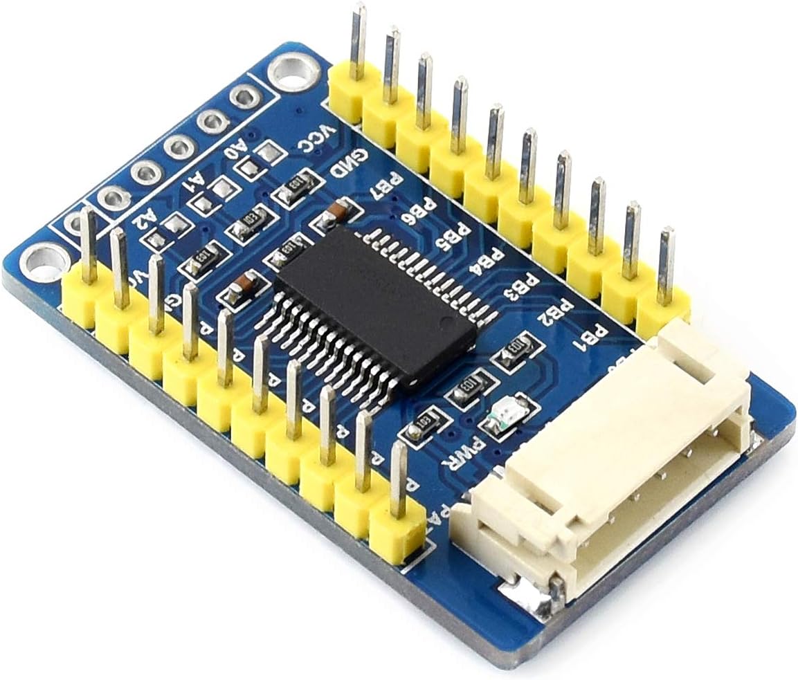
Figure 2: Pinout for VCC, GND, SDA, SCL, and I/O ports.
3.2 I2C Address Configuration
The MCP23017 chip allows for address configuration using three jumpers: A0, A1, and A2. By default, these jumpers are open, setting the I2C address to 0x20. Shorting these jumpers to GND changes the address. Each jumper corresponds to a bit in the I2C address, allowing up to 8 unique addresses (0x20 to 0x27) for stacking multiple boards.
- A0: Controls the least significant bit of the address.
- A1: Controls the middle bit of the address.
- A2: Controls the most significant bit of the address.
Refer to the MCP23017 datasheet for a detailed address table based on jumper configurations.

Figure 3: Location of A0, A1, A2 address configuration jumpers.
3.3 Stacking Multiple Boards
To use multiple MCP23017 boards, each board must have a unique I2C address. Configure the A0, A1, and A2 jumpers on each board to assign a distinct address. Connect the VCC, GND, SDA, and SCL lines of all boards in parallel to your microcontroller. The PH2.0 terminal and solder pads facilitate easy stacking and connection.
4. ຄໍາແນະນໍາການດໍາເນີນງານ
Once physically connected and addressed, the MCP23017 board can be controlled via I2C commands from your microcontroller. The 16 I/O pins are divided into two 8-bit ports, Port A (PA0-PA7) and Port B (PB0-PB7).
- Pin Direction: Each I/O pin can be configured individually as an input or output.
- Input/Output Operations: Read digital states from input pins or write digital states to output pins.
- ຂັດຂວາງ: The INTA and INTB pins can be configured to signal the microcontroller when a change occurs on specific input pins, reducing the need for continuous polling.
ສຳລັບຕົວຢ່າງການຂຽນໂປຣແກຣມລະອຽດamples and libraries compatible with Raspberry Pi, micro:bit, Arduino, and STM32, please refer to the official development resources:
Online User Manual/Schematic/Code/Datasheets

Figure 4: Included PH2.0 6-pin cable for connections.
5. ບໍາລຸງຮັກສາ
The MCP23017 IO Expansion Board is a robust electronic component, but proper handling and care will ensure its longevity:
- ຄວາມສະອາດ: Keep the board free from dust and debris. Use a soft, dry brush or compressed air for cleaning.
- ການຈັດການ: Avoid touching the electronic components directly, especially the pins, to prevent electrostatic discharge (ESD) damage. Handle the board by its edges.
- ການເກັບຮັກສາ: Store the board in an anti-static bag when not in use, in a cool, dry environment.
- ການສະຫນອງພະລັງງານ: ສະເຫມີຮັບປະກັນ voltage (3.3V or 5V) is applied to VCC. Incorrect voltage can permanently damage the board.
6. ການແກ້ໄຂບັນຫາ
If you encounter issues with your MCP23017 IO Expansion Board, consider the following troubleshooting steps:
- ບໍ່ມີການສື່ສານ:
- Verify all physical connections (VCC, GND, SDA, SCL) are secure and correct.
- Check the I2C address configuration (A0, A1, A2 jumpers) and ensure it matches the address used in your code.
- ຢືນຢັນວ່າການສະຫນອງພະລັງງານ voltage is correct (3.3V or 5V) and stable.
- Ensure your microcontroller's I2C bus is properly initialized and functioning.
- Incorrect I/O Behavior:
- Double-check your code for correct pin direction configuration (input/output).
- Verify that you are reading from/writing to the correct port (Port A or Port B) and pin numbers.
- If using interrupts, ensure the interrupt configuration and handling routine in your code are correct.
- ບອດບໍ່ໄດ້ເປີດ:
- Check the VCC and GND connections for continuity and correct polarity.
- Test your power supply to ensure it is providing the expected voltage.
For further assistance, consult the online development resources linked in the Operating Instructions section.
7. ຂໍ້ມູນຈໍາເພາະ
| ຂໍ້ມູນຈໍາເພາະ | ມູນຄ່າ |
|---|---|
| ຊື່ຕົວແບບ | MCP23017 IO Expansion Board |
| ຜູ້ຜະລິດ | Waveshare |
| ການດໍາເນີນງານ Voltage | 3.3V / 5V |
| ການໂຕ້ຕອບ | I2C |
| Expansion I/Os | 16 (8 for Port A, 8 for Port B) |
| Interrupt Pins | INTA, INTB |
| I2C Address Range | 0x20 - 0x27 (configurable) |
| ຂະໜາດ | ຂະ ໜາດ 38mm × 23mm |
| ຂະໜາດຂຸມສຳລັບຕິດຕັ້ງ | 2.0ມມ |
| UPC | 778365986900 |
8. ສະຫນັບສະຫນູນ
For comprehensive technical support, including detailed schematics, example code, and datasheets, please visit the official Waveshare development resources:
Waveshare Online Resources for MCP23017 IO Expansion Board
These resources provide examples for various platforms such as Raspberry Pi, micro:bit, Arduino, and STM32, to assist you in integrating the board into your projects.